I’m sorry to report that despite coordinated efforts between Japanese and European teams we have not been able to receive any signal from UNITEC-1 over Europe. Japanese ground stations were able to receive both the orbit determination downlink and the major/minor data downlink during the first pass after launch; however, the signal has been lost during the first mission day sometime between LOS over Japan and AOS over Europe.
UNITEC-1
Successful UNITEC-1 launch and separation!
The launch of H-IIA F17 carrying AKATSUKI, IKAROS, UNITEC-1 and three cubesats was successful! So was the separation of UNITEC-1 which was confirmed at 22:48 UTC (Epoch time 22:46:20 UTC). We meet tomorrow afternoon at OZ7SAT for the first communication window predicted to begin around 17:21 UTC. At that time UNITEC-1 will already be at … Read more
5.8 GHz Helical Feed for the 90cm dish
Yesterday was day 2 where we were repairing the broken Azimuth rotator and making a small 90cm dish ready to track UNITEC-1 on 5.84 GHz. Actually, we already fixed the rotator on Monday but we ended up mounting it 180° off and we decided to fix it properly instead of just correcting it in software.
Fixing the orientation of the Azimuth rotoator was very quick – it took only 17 minutes to get up to the mast, lift the antenna construction, change the orientation of the rotator and fasten the nuts and bolts again. We had the practice from yesterday.
Next item on the agenda was to make a small helix with two turns to feed the 90cm dish so that we can use this smaller dish for tracking UNITEC-1 in the beginning of the interplanetary cruise. We found some online helical antenna calculator to generate the design but that was more than 1 GHz off and it took a lot of tweaking and tuning to get it close to 5.8 GHz. Here are the results, photos and videos.
Smaller dish for tracking UNITEC-1
As you probably already know the UNITEC-1 launch got scrubbed today (17th May). Fortunately, there is a launch window every day for the next few weeks.
During the last few days I learned that tracking UNITEC-1 will be very difficult because the available trajectory data can be very uncertain. Therefore, we decided to use a smaller antenna with wider beam width in the first few days after launch. One option was to mount the IKEA dish to piggyback the 7m dish, another option was to use a 90cm dish which is currently equipped with a 2.4 GHz feed. We decided to go for the second option.
Preparing the 7m antenna for UNITEC-1
AMSAT OZ staff are preparing the 7 meter dish for tracking the UNITEC-1 interplanetary spacecraft. Related articles: UNITEC-1 Link Budget C-band Receiver Hardware for UNITEC-1 UNITEC-1 5.8 GHz Receiver Test Using OZ7IGY Smaller dish for tracking UNITEC-1 5.8 GHz Helical Feed for the 90cm dish UNITEC-1 Tracking Report
UNITEC-1 Link Budget
Below you will find the link budget summary calculated for a few distances during the interplanetary cruise of UNITEC-1. The link budget calculator sheet containing all the details is available here. Parameter Value Frequency 5840 MHz TX Power 4.8 W / 6.8 dBW / 36.8 dBm TX Ant Gain 5 dBi EIRP 11.8 dBW Distance … Read more
C-band Receiver Hardware for UNITEC-1
With only a few days left until the launch of UNITEC-1 (May 17) to Venus, we are getting ready to track it and I am trying to catch up on the documentation part – this time a brief description of the receiver hardware.
Recall the system architecture where the 5.84 GHz RF signal is converted to 640 MHz using the KU LNC 5659 C PRO low noise down converter, and…
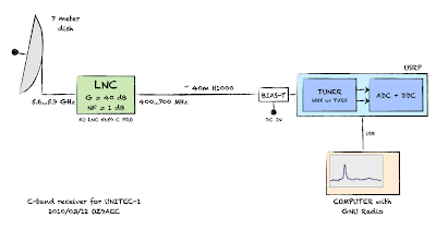
This article gives a high level walkthrough of the receiver used to convert the 640 MHz IF to digital baseband, i.e. the blue box called USRP in the above diagram.
Simple CW Receiver with GNU Radio
I have been playing with GNU Radio and GRC (GNU Radio Companion) over the weekend and I ended up implementing a very simple CW receiver. This will be very handy on Tuesday when we will be testing the 5.8 GHz UNITEC-1 setup for the first time using the OZ7IGY beacon on 5.76093 GHz. Here is a quick video demo of the receiver where I use my Yaesu FT-817ND to transmit a test signal.
Bias-T for the UNITEC-1 Receiver
Today I have been looking at the options for bias tees that we can use for the UNITEC-1 receiver. A bias tee (aka. Bias -T) is a simple device that can inject DC voltage into a coax cable. It is often used to provide supply voltage to devices that are mounted on the antenna without … Read more
Technical papers about UNITEC-1
I did a Google search to find some technical information about UNITEC-1 – in addition to what is already available on their website – and here is what came up: Structural Design of UNITEC-1 (944k PDF) UNITEC-1 and Onboard Computer Survival Competition in Interplanetary Environment (867k PDF) Preliminary Thermal Design of UNITEC-1 (1.0M PDF) They … Read more