UNITEC-1 Tracking Report

I’m sorry to report that despite coordinated efforts between Japanese and European teams we have not been able to receive any signal from UNITEC-1 over Europe. Japanese ground stations were able to receive both the orbit determination downlink and the major/minor data downlink during the first pass after launch; however, the signal has been lost during the first mission day sometime between LOS over Japan and AOS over Europe.

Continue reading “UNITEC-1 Tracking Report”

5.8 GHz Helical Feed for the 90cm dish

Yesterday was day 2 where we were repairing the broken Azimuth rotator and making a small 90cm dish ready to track UNITEC-1 on 5.84 GHz. Actually, we already fixed the rotator on Monday but we ended up mounting it 180° off and we decided to fix it properly instead of just correcting it in software.

Fixing the orientation of the Azimuth rotoator was very quick – it took only 17 minutes to get up to the mast, lift the antenna construction, change the orientation of the rotator and fasten the nuts and bolts again. We had the practice from yesterday.

Next item on the agenda was to make a small helix with two turns to feed the 90cm dish so that we can use this smaller dish for tracking UNITEC-1 in the beginning of the interplanetary cruise. We found some online helical antenna calculator to generate the design but that was more than 1 GHz off and it took a lot of tweaking and tuning to get it close to 5.8 GHz. Here are the results, photos and videos.

Continue reading “5.8 GHz Helical Feed for the 90cm dish”

Smaller dish for tracking UNITEC-1

As you probably already know the UNITEC-1 launch got scrubbed today (17th May). Fortunately, there is a launch window every day for the next few weeks.

During the last few days I learned that tracking UNITEC-1 will be very difficult because the available trajectory data can be very uncertain. Therefore, we decided to use a smaller antenna with wider beam width in the first few days after launch. One option was to mount the IKEA dish to piggyback the 7m dish, another option was to use a 90cm dish which is currently equipped with a 2.4 GHz feed. We decided to go for the second option.

Continue reading “Smaller dish for tracking UNITEC-1”

Preparing the 7m antenna for UNITEC-1

AMSAT OZ staff are preparing the 7 meter dish for tracking the UNITEC-1 interplanetary spacecraft.

Related articles:

UNITEC-1 Link Budget

Below you will find the link budget summary calculated for a few distances during the interplanetary cruise of UNITEC-1. The link budget calculator sheet containing all the details is available here.

Parameter Value
Frequency 5840 MHz
TX Power 4.8 W / 6.8 dBW / 36.8 dBm
TX Ant Gain 5 dBi
EIRP 11.8 dBW
Distance (km) 20.000 200.000 2.000.000 15.000.000 20.000.000
Distance (AU) 0.0001337 0.0013369 0.0133692 0.1002687 0.1336916
Free Space Loss 194 dB 214 dB 234 dB 251 dB 254 dB
Atm. losses 2 dB
Signal at RX ant -184 dBW -204 dBW -224 dBW -242 dBW -244 dBW
Pointing loss 0.4 dB
Receiver G/T 23 dB/K
S/N0 67 dBHz 47 dBHz 27 dBHz 10 dBHz 7 dBHz
SNR @ 500 Hz BW 40 dB 20 dB 0 dB -17 dB -20 dB
SNR @ 100 Hz BW 47 dB 27 dB 7 dB -10 dB -13 dB

Assumptions

  1. Attenuation due to rain, ionosphere and atmospheric gasses set to 2 dB[2]
  2. TX power is 4.8 watts/antenna[3].
  3. TX antenna is microstrip patch, linear, assuming 5 dBi gain[3].
  4. Our beam width is 0.5° and I assumed a pointing error no greater than 0.1° (very optimistic) giving a 0.4 dB pointing loss.

TBDs and TBCs

  1. Measure the receiver noise floor, i.e. local interference contribution to sky temperature (important)
  2. Re-assess sky noise taking expected solar noise, etc. into account[2]

Conclusions

  1. An optimistic estimate suggests that we should be able to receive UNITEC-1 up to 10-15 million km distance.
  2. There is plenty of margin in the beginning and we can use a low gain antenna for initial acquisition. The IKEA dish has ~25 dBi gain and it could be used up to 1 million km where after the trajectory is hopefully well known.

Related Articles

C-band Receiver Hardware for UNITEC-1

With only a few days left until the launch of UNITEC-1 (May 17) to Venus, we are getting ready to track it and I am trying to catch up on the documentation part – this time a brief description of the receiver hardware.

Recall the system architecture where the 5.84 GHz RF signal is converted to 640 MHz using the KU LNC 5659 C PRO low noise down converter, and…

C-band receiver architecture

This article gives a high level walkthrough of the receiver used to convert the 640 MHz IF to digital baseband, i.e. the blue box called USRP in the above diagram.

Continue reading “C-band Receiver Hardware for UNITEC-1”

Technical papers about UNITEC-1

I did a Google search to find some technical information about UNITEC-1 – in addition to what is already available on their website – and here is what came up:

They all appear to be from the same conference held last year.

I also found two videos on YouTube, one showing a 20 second flight sequence, and one longer that appears to give a presentation of UNITEC-1; however, it is in Japanese so I have no idea what they say 🙂

If you find something else interesting about UNITEC-1, technical papers, videos or something else, leave a comment!

Submissions received so far:

UNITEC-1: The KU LNC 5659 C PRO has arrived

Yesterday I have received the C-band down-converter that I have ordered last week for the UNITEC-1 receiver station.

Watch video on YouTube.

I have also uploaded a few high resolution photos to my Picasa Albums:

Close-up the KU LNC 5659 C PRO low noise downconverter (LNC) from Kuhne Electronic.

Close-up the KU LNC 5659 C PRO low noise downconverter (LNC) from Kuhne Electronic.

The KU LNC 5659 C PRO low noise downconverter (LNC) from Kuhne Electronic. It converts 5.6...5.9 GHz to 400...700 MHz. Noise figure 1 dB, Gain 40 dB.

If you can’t read the specs, you can see them on my work-in-progress wiki page about the C-band Receiver Station.

Next step will be to connect it to the USRP equipped with the WBX and TVRX daughterboards (need 400…700 MHz receiver) and use some basic GNU Radio receiver software to test it using the OZ7IGY beacon, which transmits on 5.7 GHz (5760.930 MHz to be precise) and is definitely within our range. We can probably also find a signal generator for 5.6/5.7/5.8/5.9 GHz somewhere for better tests.

UNITEC-1: A New Deep Space Adventure

If everything goes according to current plans, JAXA will launch their PLANET-C spacecraft towards Venus on May 18, 2010. To fill out the empty space and available payload mass on the H-IIA rocket, they will also bring four university built cubesats into orbit. One of these cubesats, UNITEC-1, is very special in that it will follow PLANET-C all the way to Venus, although without any propulsive capabilities to make trajectory corrections it might end up somewhere else – we’ll see about that. Another special thing about UNITEC-1 is that it will be using the 6 cm amateur radio band. Cubesats have a tendency to be stuck on VHF and UHF frequencies for understandable reasons, so a 5.8 GHz signal from deep space will be an interesting challenge!

Our Mission

The mission for us radio amateurs is much more than just trying to listen for UNITEC-1. As I see it, radio amateurs can:

  1. Receive telemetry from an interplanetary spacecraft. UNITEC-1 will transmit telemetry on 5.84 GHz using very simple ON/OFF keying at 1 bit per second. This is quite exciting – I believe it will be the first time that we can receive unencrypted telemetry from an interplanetary spacecraft.
  2. Support the UNITEC-1 operators by tracking their craft. By providing them with accurate measurements of antenna pointing and Doppler shift, the operators can estimate the actual trajectory of the craft (remember, UNITEC-1 does not have any coherent tracking transponder on-board). More tracking data from around the world will improve their statistics significantly.

There is a formal call for support on the UNITEC-1 website requesting the global amateur radio community to help with tracking. You can also read about the actual mission UNITEC-1 will carry out during its journey to Venus. Be sure to check out the PDF file that gives many details relevant to tracking.

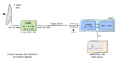
System Overview

We plan on assembling a system consisting of:

  • The 7 meter parabolic dish at OZ7SAT
  • A wide band feed that should be good up to 10 GHz
  • A Low noise down-converter (LNC)
  • Universal Software Radio Peripheral (USRP) with an appropriate RF daughterboard (probably WBX trasceiver or TVRX receiver)
  • GNU Radio-based software defined radio receiver

Functional diagram of the C-band receiver

We are going to need a C-band downconverter. From Kuhne we have several choices. One kind uses 1.4…1.7 GHz as IF, the other kind uses 400…700 MHz as IF. Since we already have about 40 meters of H1000-class cable between the antenna and the control room, we chose the UHF version to reduce the cable losses.

The LNC has been ordered and it should arrive next week. We have everything else on stock but will need to write some software. There is plenty of time though until 17 May. In any case, stay tuned for updates during the coming weeks.


Related articles: