Yesterday I finished the IF section and the TX mixer. Today I finished the last two sections, namely the TX driver and power amplifier. There were a few dificculties along the way…
Receiver Alignments
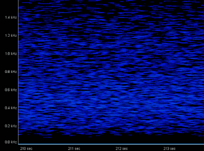
This is what I was supposed to do after finishing the IF stage. There was actually not much to align, since the only adjustable parameter is the BFO offset. First, I hooked up my noise generator to the input of the TCA440 IF amplifier (MP5 in the sparrow manual) to make sure that the sigfnal was coming through. I observed the audio signal using a PC sound card spectrum scope:
Next, I moved the noise source to the filter input, MP6, and was overwhelmed to see that only 400 Hz of noise was coming out at the other end. The filter was working! The center frequency was way too low, something like 300 Hz, but I could easily move it by adjusting C94. I have set it to 800 Hz, which corresponds to the trimmer being at the middle position.

This completes the tests of section 3.
I have also tested section 4, the VFO mixer. The manual suggests the use of a receiver to align the filters. This was, however, quite impossible because the output signals are way too strong (hundreds of milli volts), so I used my oscilloscope instead. Alignment went all right but I had to remove one turn from L4 – better that have to rewind the whole coil. I didn’t achieve higher output level by doing this, but I could find a maximum for C96.
Next, I tested the full receiver. I used the elecraft signal generator with 50uV to align the filters in the input and receiver preselector. Everything went fine, C100 was, however, a little difficult because it was very sensitive to touching. When I was satisfied I could hear the 1uV signal as well. It was very weak, but that can be due to additional losses in the cable from the signal generator to the receiver input (it was not 50 ohm cable). In any case, it will probably be a good idea to redo these alignments on the fully finished sparrow with an s-meter attached to the AGC circuit (for now it is only shorted).
TX Mixer
This was part of section 6. I aligned the filters using the FT-817 receiver hooked directly to the mixer output. The signal was rather strong, but enabling both IPO and ATT I could actually detect a maximum. The trimmer capacitors were very close to their minimum values, but it looks like I don’t have to adjust any of the coils. In any case, the important matter at the end is to obtain the 5 watts.
Driver and PA
Finishing these two sections was not without trouble.
First, T5 needs a ferrite bead on its collector and it seems rather impossible to mount it without making a short between the two adjacent legs. I felt it absolutely necessary to isolate the ferrite with some thin plastic tape.
Sencond, it was quite a challenge to wind L8: 30 turns primary + 16 turns secondary on a T37-2 with 0.3 mm wire. It was very difficult to make it fit and I went well over the 270 deg coverage.
The filter alignment went all right. I was very happy that I didn’t have to rewind L8 :o)
I did, however, put a 1k resistor in parallel with R29, 22k, in order to allow higher gain, in case it should be necessary. I calibrated the DL1 dummy load power read-out using the FT-817 and then I used this calibration to have and idea of the power output. With the gain adjusted to maximum the output was somewhere around 15-20 watts! I replaced the 1k resistor with a 2k2 one (so that the total series resitance was 1k1) and the power output was still adjustable between 0-6 watts. I left it around 1 watts as suggested by the manual.
The final tests before mounting the sparrow in the enclosure will consist of a complete mockup including RIT/XIT buttons and keyer.