99.5% of the people who built at least one K1 enjoyed doing so and I am no exception. This article summarizes my K1 building experience hoping that other prospective K1 builderswill find it useful.
A basic K1 consists of three circuit boards:
- The main RF board.
- Front panel board with the microcontroller.
- The filter board for either 2 or 4 bands.
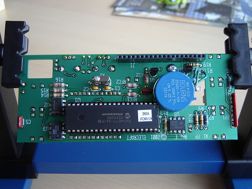
Optionally, one can add a noise blanker and an internal automatic antenna tuner. Each of these come with their own PCB and fit perfectly into the small box. In fact, the K1 is very well designed when it comes to connecting the various boards together. Instead of wires, the K1 boards are assembled with connectors mounted on the PCBs, and this gives a very professional feel during assembly, see the picture below.
The Filter Board
Assembly started with the filter board. The manual contained instructions for the two-band module, while the instructions for the four-band module were included separately with the parts.
I bought the four-band module and so I had a lot of fun winding the toroids. Many people are afraid of winding toroids or find it boring. I myself enjoyed it because I knew that properly wound toroids will make a big difference in the end.
The turns on toroids had to be evenly distributed and take up about 80-90% of the core. I found it to be a good idea to start with the highest band needing the fewest turns and work gradually down.
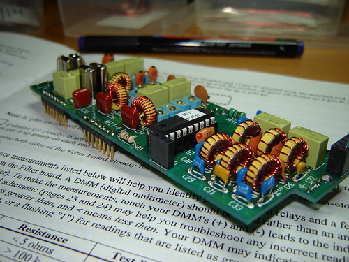
The four-band filter board came with 40, 30, 20, and either 17 on 15 meter bands. I could chose at build time whether I wanted 17 or 15. I chose 17. Although the two-band module can be built for 80 m eters too, it was not available with the four-band module. This has to do with the way the filters have been designed. In order to save space 40+30 and 20+17/15 filters share some parts with each other.
When the filter board was finished I made the resistance checks and everything checked out fine. Further tests and alignments are performed after finishing the RF board.
Front Panel Board
I have started the assembly of my K1 with the front panel board. This PCB is mounted directly onto the front panel (hence the name) and it hosts the LCD, push buttons, potentiometers and the MCU. Already here I was amazed by the fact that the resistors were in a strip in the same order as they should be mounted. Really cool!
I only came across one minor oddity while assembling the board. The LCD backlight mod kit has to be applied after the MCU has been placed into its socket. What I found odd here is that the first step in the LCD modkit is to remove the MCU again, which is not that trivial due to the size of the MCU. Tom NØSS told me that is so because the modkit was originally designed for already built K1s. Well, that made sense, still, this modkit is for unbuilt K1s so I don’t quite understand why it isn’t applied before mounting the MCU into its socket. Of course, I could have spared myself from the confusion if I would have read the instructions completely before starting the work.
Otherwise, I can assure you that the manual was very clear on how to mount the parts. This was very important in order to achieve correct spacing of the push buttons.
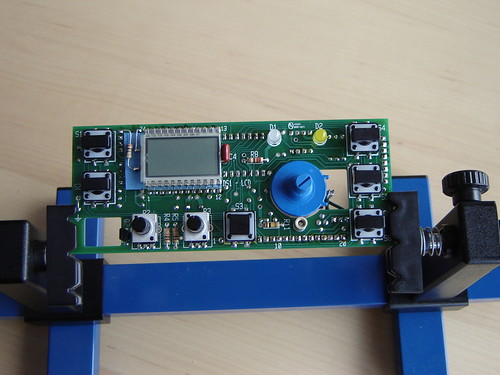
Mounting the LCD and the modkit was a little difficult because there was little space due to the already mounted potentiometers. Next time I will wait with the potentiometers till after the LCD is mounted. As you can see on the picture I chose the 200 ohm resistor for the backlight to get brighter display but at the cost of 3-4 milliamps.
During soldering the LCD I learned that my soldering station is not ESD safe. Every time I was soldering a pin of the LCD the corresponding segment lit up slightly. Quite worrying, but I can tell you now that the LCD survived without any noticeable damage.
When the front panel board is assembled the manual lists a series of resistance checks that can be done to verify some obvious cold soldering or shorts. All the checks passed fine for me the first time.
After finishing the front panel board I still had three resistors left. Nothing to worry about, this can be normal for Elecraft kits.
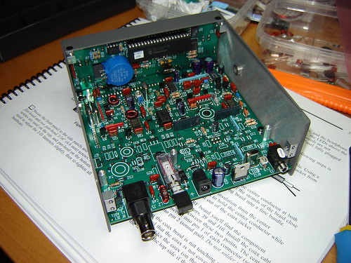
RF Board
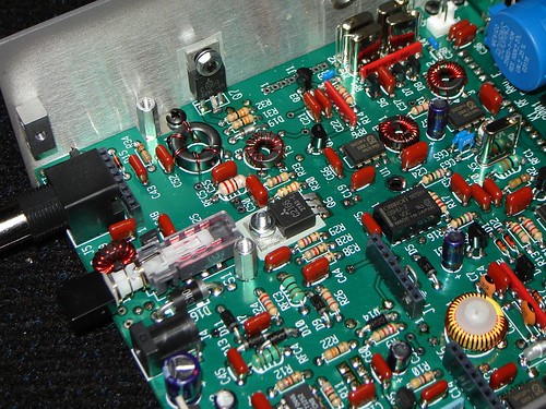
The RF board is the main board in the K1 containing VFO, IF, AF, and TR switching. The assembly consists of two parts, part 1 concerns the VFO and receiver, while part 2 completes the board with the transmitter.
Assembling the RF board took some time. There were many parts and there were also a few toroids to wind.
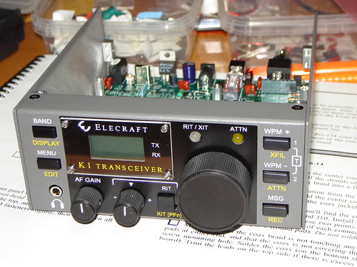
When part 1 was finished, the RF board was mated with the front panel board and the K1 was alive! After some initial tests, the RF alignment was performed using the built-in measurement functions in the MCU. After the VFO alignment the filter board was mounted on top and aligned for reception. I felt that it was an advantage to have either a signal generator or a transmitter for the bands covered by the K1. I used my FT-817ND and a dummy load.
The picture on the top of this page shows my K1 after finishing part 1 of the RF board and mating with the front panel board. Needless to say, the two boards fit together perfectly!
I took several attempts at aligning the filter board for reception. I didn’t quite succeed in acquiring optimal peaks on all bands. You can try to read my blog for details. Eventually, I ended up with a quite satisfactory result:
- 20/17: Good strong signal. No difference if I put my fingers close to the filter board. It wasn’t difficult to hear the 1uV signal from the XG-2 on 20 even with attenuator ON!
- 30: Relatively good. I could approach the filter board with my fingers without making any difference.
- 40: Very similar to 30. The 1uV signal from the XG-2 was not strong but hearable even with the attenuator ON.
I was quite satisfied with these results. The sensitivity on 40 meters was not as good as on 20 and 17, but you do not need high sensitivity on 40 in Europe! On the contrary.
Assembly of part 2 went smoothly. I did not encounter any problems. I did not bother to remove the front panel nor the side panels as instructed by the manual, so space was a little tight while mounting some of the part. But there were no problems at all, in fact, I believe it was much easier to fit and mount the PA transistor without removing the right side panel. The resistance checks were all fine. Now it was time to the transmitter alignment.
I was just about to panic when I first set the K1 into TUNE mode. I have hooked up the K1 to my variable power supply, set the current limiter to 1 amps (as instructed by the manual), turned the K1 on and set it into TUNE mode. The only thing that happened was that the K1 turned off and the current limit indicator led on my power supply lit up; the K1 wanted more current then it was given!
I tried to give it more current but there seemed to be no limit on how much current the K1 wanted. Above 1.25 amps the K1 could stay turned on, but the behavior did not seem normal at all. It should not draw so much current, since the transmitter is actually off with the initial power setting at 0.0 watts and the filter board missing. Something was very wrong. I tried to do one or two voltage checks but, of course, they were way out of range.
I started to look for bad solderings, misplaced or missing parts and suddenly I noticed that D11 was mounted reversed… I unsoldered it and remounted it, this time on the bottom side of the PCB because the top side got slightly damaged. Turned the K1 on and suddenly it looked much better…. phew….
Voltage checks were now perfect and the transmitter alignment procedure went fine, too. The built-in instruments in the K1 were really priceless. The TX offset adjustment went good, too.
At this point the basic K1 was finished! I finished the assembly and attached the ATX-1080 antenna. I could copy some stations but they were rather weak. After all, I was using a compromise antenna indoors.
Noise Blanker
The noise blanker is a small add-on board to the K1 that can reduce electrical pulse-type noise. There are two things I would like to mention regarding the KNB1.
First, according to the errata sheet, I had to mount C14 on the bottom of the board between pins 1 and 8 of U1. This had to be done before U1 was mounted. If so, how on earth would I be able to mount U1 afterwards? Surely the holes for pin 1 and 8 would be filled with tin if I would have soldered the capacitor before I soldered U1 in. Thus, I waited with mounting C14 till after U1 was in place and I believe this was a very good decision.
Second, the noise blanker board had to be secured using a screw and a standoff. The standoff was installed with an internal-tooth lock washer and a nut. It looked to me, however, that it was impossible to mount the nut and the lock washer without them touching a close-by circuitry. I wondered whether the green paint got damaged while tightening the nut…
Besides that, the noise blanker appeared to work all rught. I did not actually remove any noise but I could at least tune the circuit by adjustning the variable capacitor. So something was happening in there.
KAT1 ATU
I have not assembled the KAT1 yet. I have assembled the KAT1 now, but I need to update this page…
Conclusion
The K1 was definitely one of the most enjoyable kits I have ever assembled. In many ways, the K1 is a very controversial radio kit. On one hand, it is simple, easy to build, and easy to understand. There are no surface mount part, and there is in fact very good space on the PCBs; at least if one follows the assembly instructions. On the other hand, the K1 uses state of the art micro-controller technology to manage complex functions and provide the user with bells and whistles only known from commercial radios. And you have a feeling already from the beginning, when you open the box, that you are about to build a top professional radio. This is very motivating during the assembly of the kit.
The assembly manual is very good. It describes step by step what to do and points at possible pitfalls. The instructions are often accompanied by illustrative drawings and, in case the instructions are not adequate, there is a lot of help to get from the world wide user community. The alignment…
Both the PCBs and the ready made enclosure is of good quality. Everything fits together flawlessly and it is very easy to open the box in case you need to do some adjustments. Raw enclosures can be bought on their own and I think they are very well suited for other homebrew projects.
From time to time you may run into difficulties figuring out how a part should be placed because the silk screen outline is covered by the solder mask. In these cases you can use the parts placement drawing at the back of the assembly manual where one can clearly see how the parts should be mounted. There is even a searchable version on Toms Elecraft page.
I have now built my first K1 for 40, 30, 20, and 17 meters. I am sure that I will build more of them, probably two-band versions for 160+80 and other combinations. But first of all, I shall enjoy this one on the air.