With only a few days left until the launch of UNITEC-1 (May 17) to Venus, we are getting ready to track it and I am trying to catch up on the documentation part – this time a brief description of the receiver hardware.
Recall the system architecture where the 5.84 GHz RF signal is converted to 640 MHz using the KU LNC 5659 C PRO low noise down converter, and…
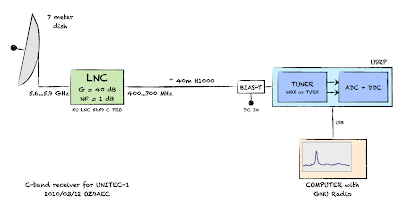
This article gives a high level walkthrough of the receiver used to convert the 640 MHz IF to digital baseband, i.e. the blue box called USRP in the above diagram.
 The receiver hardware is based on the Universal Software Radio Peripheral (USRP) equipped with a WBX transceiver board. On the receiver side, it is a direct conversion software defined radio receiver architecture where the RF is converted to baseband using a quadrature demodulator (ADL5387), digitized using 12 bit A/D converters (AD9862) and down-sampled using an FPGA. The resulting digital data is 16 bit signed I/Q that is sent to the host computer via USB2 interface.
The USRP Architecture
The USRP can host 2 receivers and 2 transmitters that can work at the same time sharing a total bandwidth of 8 MHz. Note that the ADCs are clocked at 64 MHz but the effective bandwidth is limited by the USB 2.0 interface to the host computer.
When we take all the protocol and other overhead away, USB 2.0 gives us 32 Mbytes/sec data rate. The USRP1 uses complex 16 bit signed integers (4 bytes/sample) and therefore we get 8 Msps. Since we use complex processing this gives a maximum effective total bandwidth of 8 MHz.

The WBX Receiver
The WBX is a full duplex transceiver board covering 50 MHz – 2.2 GHz. For this project we are only concerned with the receiver.
| WBX Receiver Specifications |  |
|
| Rev | 2 | |
| Frequency | 50 MHz – 2.2 GHz | |
| Noise Figure | 5-6 dB | |
| Sensitivity (CW) | Better than -130 dBm | |
| IIP2 | 40-55 dBm | |
| IIP3 | 5-10 dBm | |
| AGC Range |
70 dB – see brochure (PDF) |
|
| Antenna | TX/RX and RX2 | |
A block diagram of the WBX receiver is shown below. The detailed schematics are available from Ettus Research website.
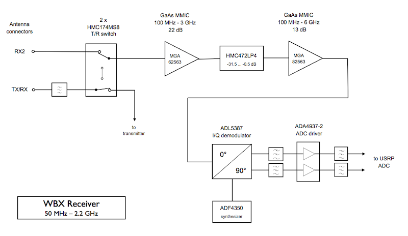
- Two HMC174MS8 GaAs MMIC T/R switches are used to configure the connection between antenna connectors and receiver/transmitter. We will use the RX2 input so that we only have one switch in the loop (estimated 0.5 dB improvement).
- MGA-62563 GaAs MMIC low noise amplifier gives 22dB gain at 0.9 dB noise figure.
- HMC472LP4 is a broadband 6-bit GaAs IC digital attenuator programmable in 0.5 dB steps.
- MGA-82563 GaAs MMIC driver amplifier gives additional 13 dB gain at 2.2 dB noise figure.
- ADL5387 50 MHz to 2 GHz quadrature I/Q demodulator converts the RF to complex baseband signal.
- ADF4350 wideband synthesizer provides local oscillator signal for the I/Q demodulator.
- ADA4937-2 low distortion differential ADC driver brings the signal up to level suitable for the ADC. The ADC full scale is 2 Vpp / 50Ω differential but there is also a 20dB PGA reducing the required input level to 0.2 Vpp.
The USRP FPGA
The FPGA contains the digital down-converter that decimates the data to fit within the 8 MHz we can transfer over the USB. Actually, the decimation is variable between 8 and 256 allowing for bandwidth as low as 250 kHz (64MHz/256). The decimation factor is distributed between a four stage decimating Cascaded integrator-comb filter and a 31 tap halfband filter that decimates by 2, see the diagram below which was taken from the USRP FAQ.
The USRP specs below were taken from the USRP brochure (PDF).
| USRP Receiver Specifications | 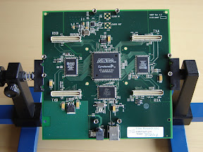 |
|
| Rev | 1.7? | |
| Sample Rate | 64 Ms/s | |
| Resolution | 12 bits | |
| SFDR | 85 dB | |
| Max Bandwidth | 16 MHz | |
| Host Interface | USB 2.0 | |

Note that the FPGA design also includes a mixer and an oscillator (NCO) which allows the use of intermediate frequency input instead of baseband. This is very useful when we use an RF front end like the TVRX which outputs a 6 MHz wide spectrum centered around 5.75 MHz. Other RF boards output baseband signal centered around 0 Hz; however, the NCO is also useful for these board. The local oscillators on the RF boards have a limited resolution that does not always (read rarely) allows tuning to the exact frequency requested by the user. Using the NCO we can compensate for this difference. Fortunately, this is done automatically by the USRP and/or the GNU Radio driver and we don’t have to worry about it.
That’s basically it! What ‘s left is GNU Radio software running on a linux PC.
I tried to be as accurate as I could; however, if you spot any mistakes in my understanding or description please let me know!
For more technical details about the USRP I can recommend Exploring GNU Radio by Eric Blossom and The USRP under 1.5X Magnifying Lens! aka. USRP FAQ.
Related articles: