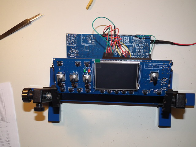
After completing the UI board I really wanted to see it work and test it one way or other without the RF board.
First, I needed to find some power supply. The UI board needs 8V, 5V and 3V, so the easiest is to assemble the power supply unit located on the RF board and connect the power and ground connection using wires. hat’s why I ended up with this breadboard like setup.
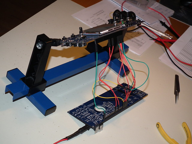
It’s a good idea to test the power supply on its own before connecting the two boards. After all, we don’t want the magic smoke to leave the MCU! After the power supply checked out, I connected the two boards and switched it on. The only thing I observed was that the LCD backlight went ON while the power button was pressed. Not surprising given that the MCU was completely blank.
Chris M0NKA has detailed instructions on how to program the bootloader and then the firmware. I followed the instructions and this is what I ended up with:
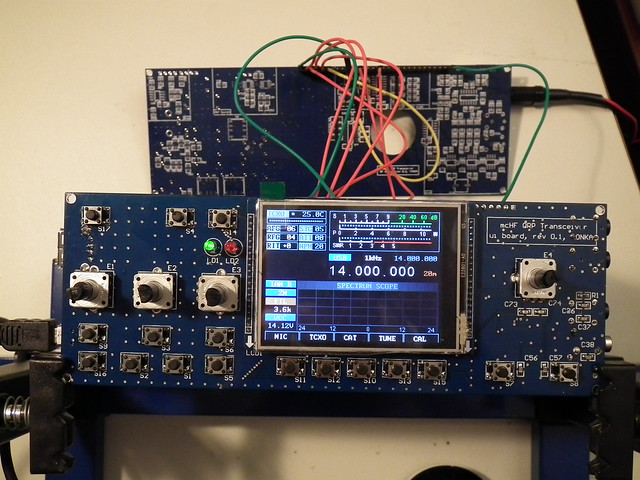
My UI board is alive. Below is a short video showing the power-on and power-off:
I can also press buttons and observe changes on the display. I didn’t perform any thorough test yet as it’s getting late now but it looks like most button presses and encoder actions have effect on the display, which I interpret as a good thing. a few things I noticed while playing with the board:
- U3 and U4 are getting hot. They certainly need a heat sink.
- VCC reads 14.1 volt event though the supply is 12 volts.